Bastion Fort – French & Indian War:
I have always been fascinated by fortification engineering, particularly bastion forts from the French & Indian War Period. Some after viewing UK Reb’s diorama pages and Mike Miller’s dioramas, I started researching into bastion fort design with the far back in the mind idea of someday modeling a bastion fort.
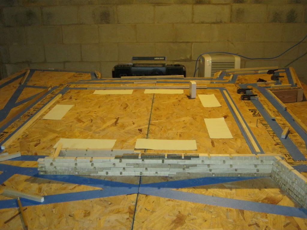
There was a web page Civil War Fortifications (defunk now) that contained a wealth of information via their Dictionary Page. Contained on that page were the guidelines and rules for developing fortifications including “tracing” a bastion fort --- developing the outline for a bastion fort. Although the outline of the bastion fort changes angles repeatedly, the outlining of the fort is very easy, it does not rely on drawing angles, but on simple intersecting lines. As such, developing the outline is straightforward and not at all difficult. The only angle that one needs to determine are 90 degree angles and any math involved is maybe 5th grade level.
I learned to trace bastion forts using this method of intersecting lines. Eventually, I took a protractor to my scale drawings to determine angles. I was surprised and very happy to find that there were only 2 resulting angles for a 4-sided bastion fort, 60 degrees and 75 degrees. Two of the standard hard stops on any miter box or power sander.
The principle idea behind a bastion fort is to have fields of fire to all points surrounding the fort and not have any defensive blind spots along the walls were an attacker could “hide” and not be fired upon by the defenders. At least from some vantage point on the wall, the defender has to be able to see and fire upon any attacking force that is hugging perimeter wall.
A B
D C
As such, the concept of a bastion fort is largely based on mutual protection - Bastion A protects the Walls of Bastion B and D while Bastion B protects the Walls of Bastion A and C, etc.
The fort I am modeling is not of a specific historical fort. But a fusion of several different concepts that were part of various forts constructed during the French & Indian War and the Revolutionary War – Fort Stanwix, Fort Ligioner, Fort Duquesne and Fort William Henry.
A principle concept of a bastion fort is to withstand some measure of artillery fire. As such, one determines what guns are likely to be used against the fort which then determines the thickness of the ramparts and parapets you need to build. Even if you assume a small caliber artillery piece such as a 6-pounder, the wall thickness to withstand a hit would be about 10 feet (6 feet penetration from the cannonball plus 50% more for a safety factor to allow the wall to remain standing). To accept the recoil from the defending artillery and have room to operate the gun, the artillery platforms behind the upper wall has to be at least 15 feet long. So if you are trying to utilize minimum values for your wall thicknesses, the wall thickness at the base is at least 25 feet (10 feet + 15 feet). At 60 mm scale, 25 feet = 10 inches. An upper parapet thickness of 15 feet would “allow” for attacking guns of a somewhat larger caliber, but the base wall thickness would then be increased to 30 feet (Fort William Henry).
The thickness of upper wall is critical in determining the overall dimensions of the fort. Again, the defense of any specific bastion is derived from the adjacent bastions. As such, you have to be able to “see” over the wall to ground level. Assuming a wall height of about 15 feet and an upper parapet thickness of 15 feet, the individual bastions have to be a minimum of 300-350 feet apart to eliminate any blind spots along the walls. If any closer, there will be safe spots adjacent to the walls were the defenders cannot see from neither of the adjacent bastions, never mind concentrating any defensive fire against that blind spot.
So unless you are willing to introduce a fatal flaw into the design, the minimum size for a bastion fort is 300 feet by 300 feet - (a better minimum would actually be a tad larger, Fort William Henry was about 325 by 350 feet). If taken to 60 scale, our model 300 ft. x 300 ft. structure is now 120 inches x 120 inches or 10 feet x 10 feet. This is simply too big to model.
But as the basement has a dehumidifier, not all hope was lost. After a lot of thought and delay, I decided to go for a 90 inch x 90 inch bastion fort (225 foot x 225 foot). The model would then by 7.5 feet x 7.5 feet. This is larger than Fort Duquesne (160 ft. x 160 ft.), but introduces a considerable number of design flaws (weaknesses) that are actually damm annoying. Dimensions smaller than 225 feet generate problems because the artillery platforms overlap (guns on recoil crashing into one another) and the flank gun embrasure is lost.
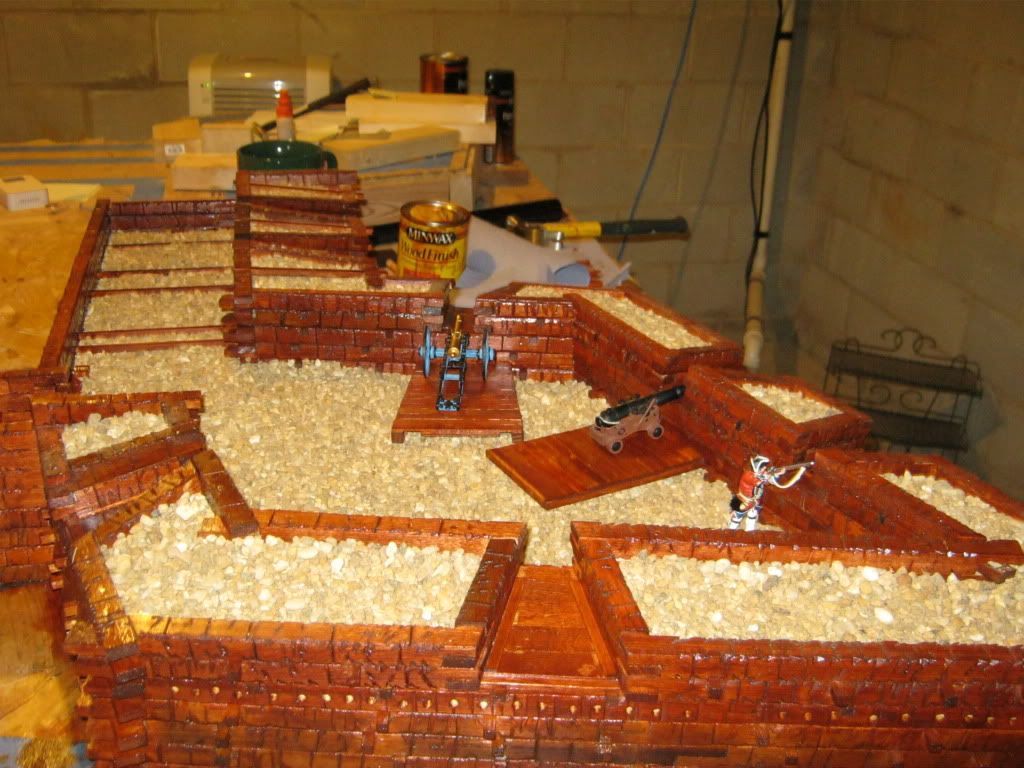
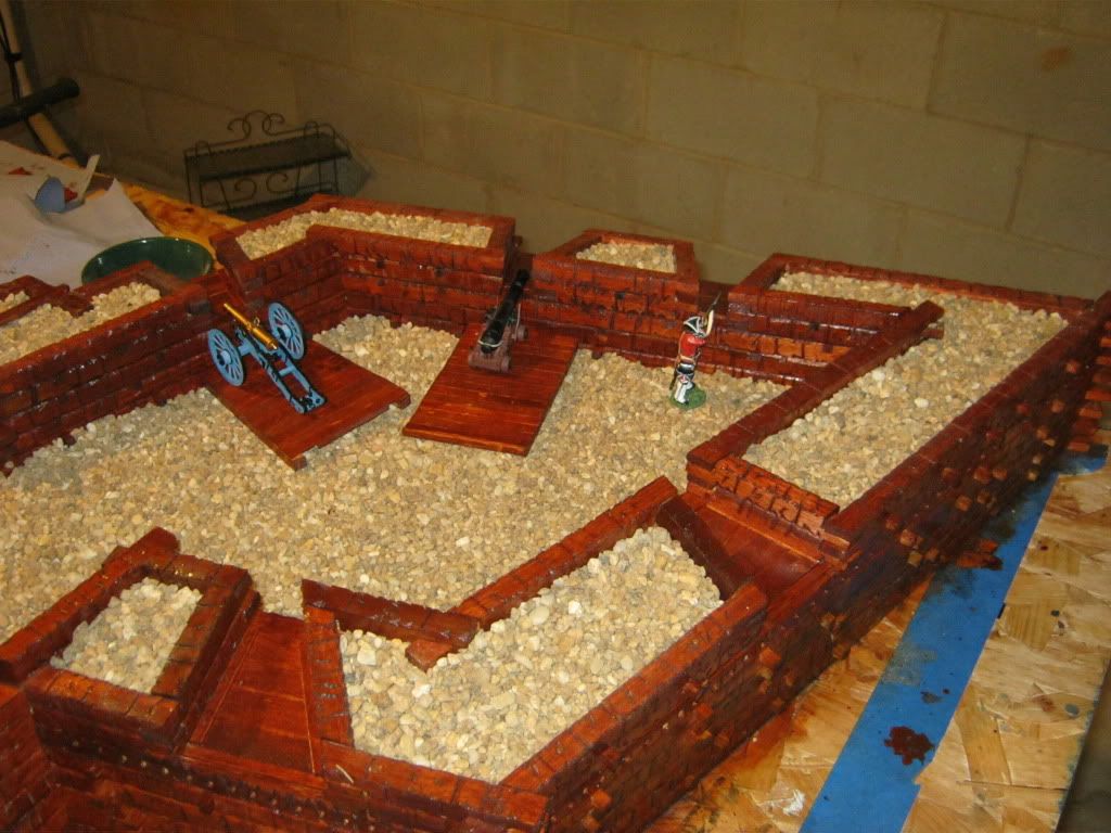
There are only three types of walls to a bastion fort. The long walls of the bastion = Face, short walls = Flank, and the walls connecting the various bastions are the Curtain Walls.
With the 225-foot design, things become very crowded, very fast. The square footage for a 225 x 225 foot is less than 60% of the 300 x 300 foot bastion. At 300 ft X 300 ft, the interior open space for the individual bastions would have been so much larger and much more attractive than the 225-ft design I ended up with. Excluding the wall thickness, the open space within the modeled 225-ft bastion is only about 15 inches by 15 inches.
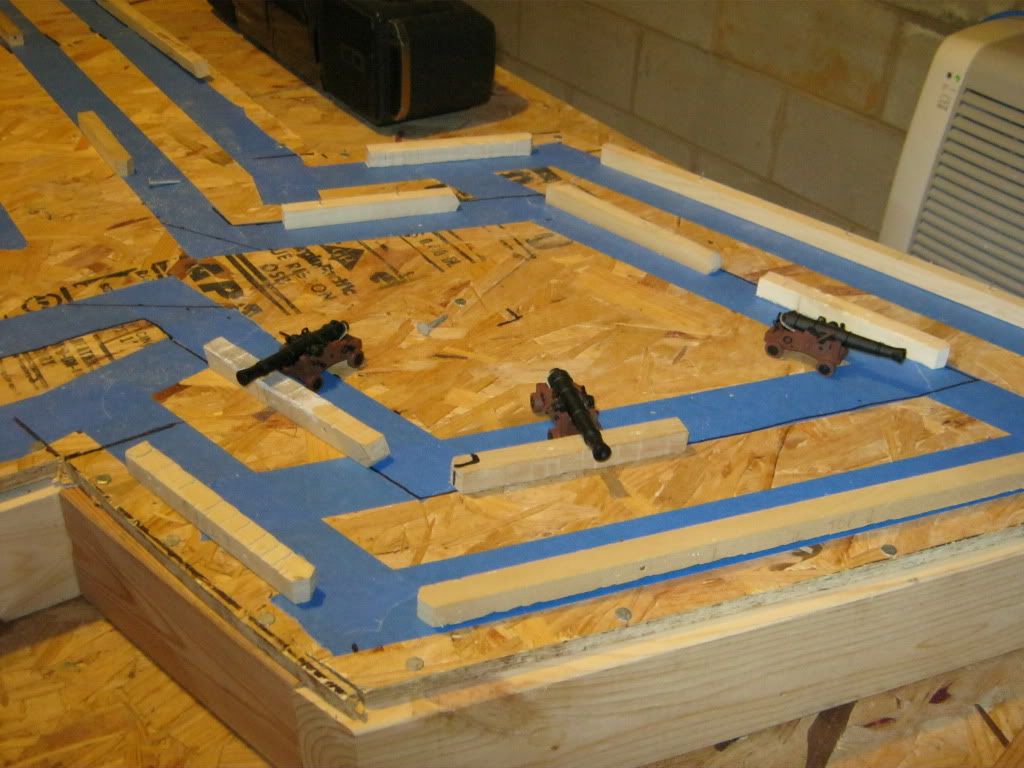
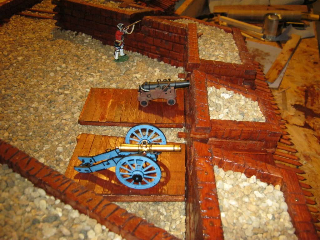
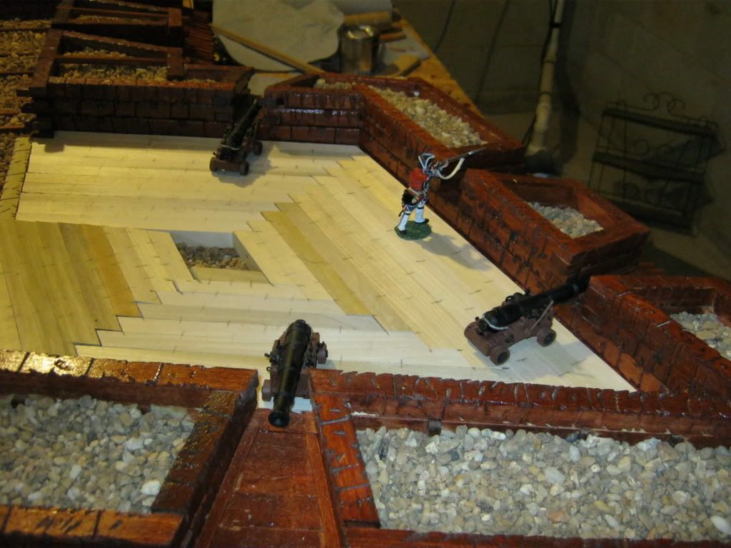
Among the design flaws I introduced in order to save space is the reduction of the upper parapet thickness on the bastion walls from the desired 15 ft to 10 feet. I left the parapet thickness on the curtain wall at 15 feet. The gun platform length was left at 15 feet. With a 300-foot design, each bastion could have probably supported 7 guns comfortably, but only 5 guns at 225 ft. Losing a gun position on each face of the bastion hurts. Ideally, there should be 2 guns in each flank of the bastion, instead of the one gun, but getting 2 guns into the flanks probably would have needed at least a 350-foot design or 375-foot design. The guns located in the flanks are key to the defense. I could have squeezed in more gun embrasures, but they are very time consuming to build and I did not want to crowd the model. In most forts the number of embrasures (gun ports) far exceeded the actual number of cannon several times over.
Google Book is a great resource for historical military manuals and old books. Often non-copyrighted materials are fully viewable. Simply go into google book and start searches from there. I have again access to dozens of military engineering manuals and texts from the period 1700’s and 1800’s. From these sources, I developed a good idea about the construction of gun embrasures, dimensions and such. Here I cheated some, the narrow neck of the gun port should only be 2-foot wide - less than an inch at 60 scale (0.8 inches). In some cases, the narrow neck of the gun ports are considerably wider to allow a broader field of fire, but the military manuals of the time strongly advise against the narrow opening being more than 2-foot wide. Sometimes this wider neck was intentional to compensation for the low number of embrasures, other times - just sloppy construction on my part.
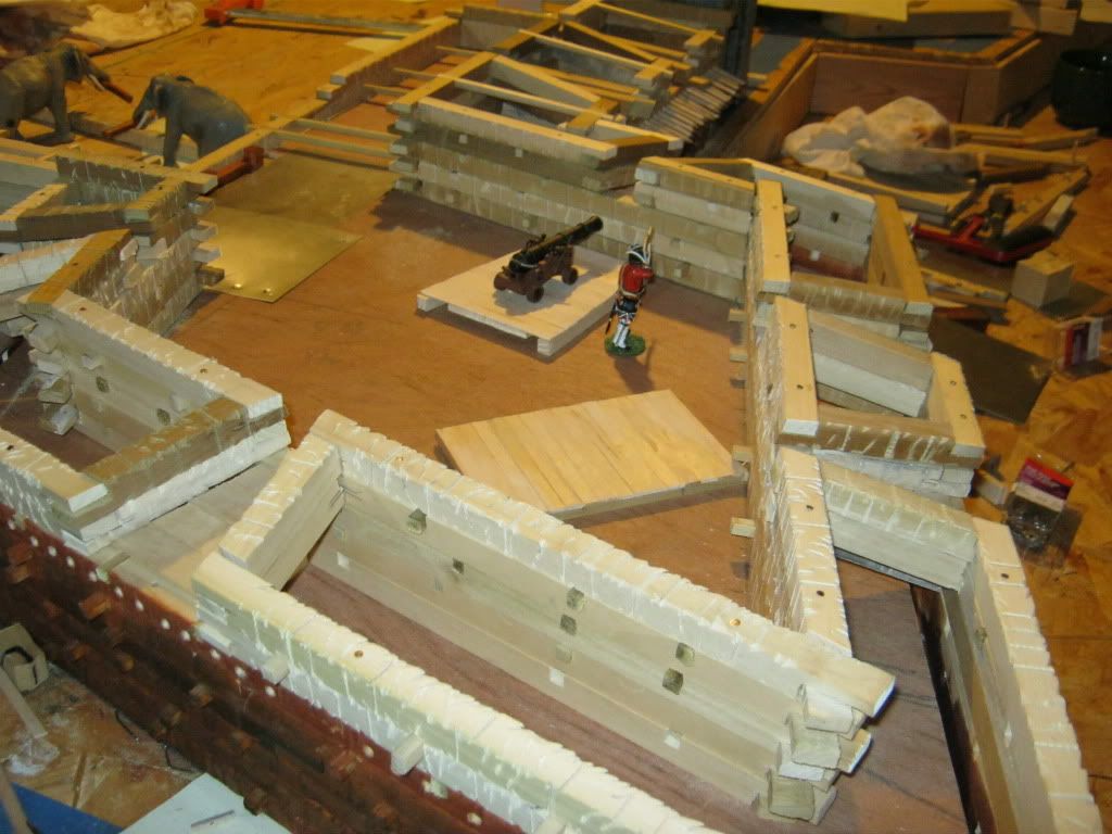
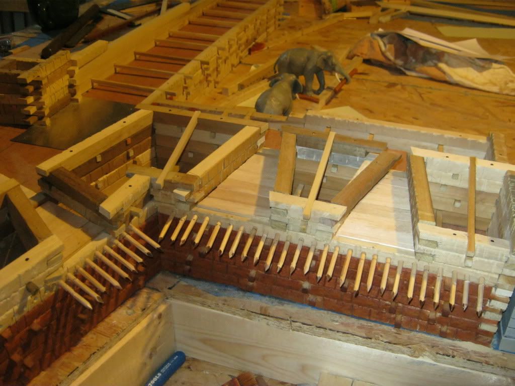
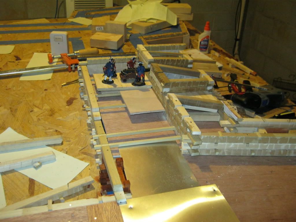
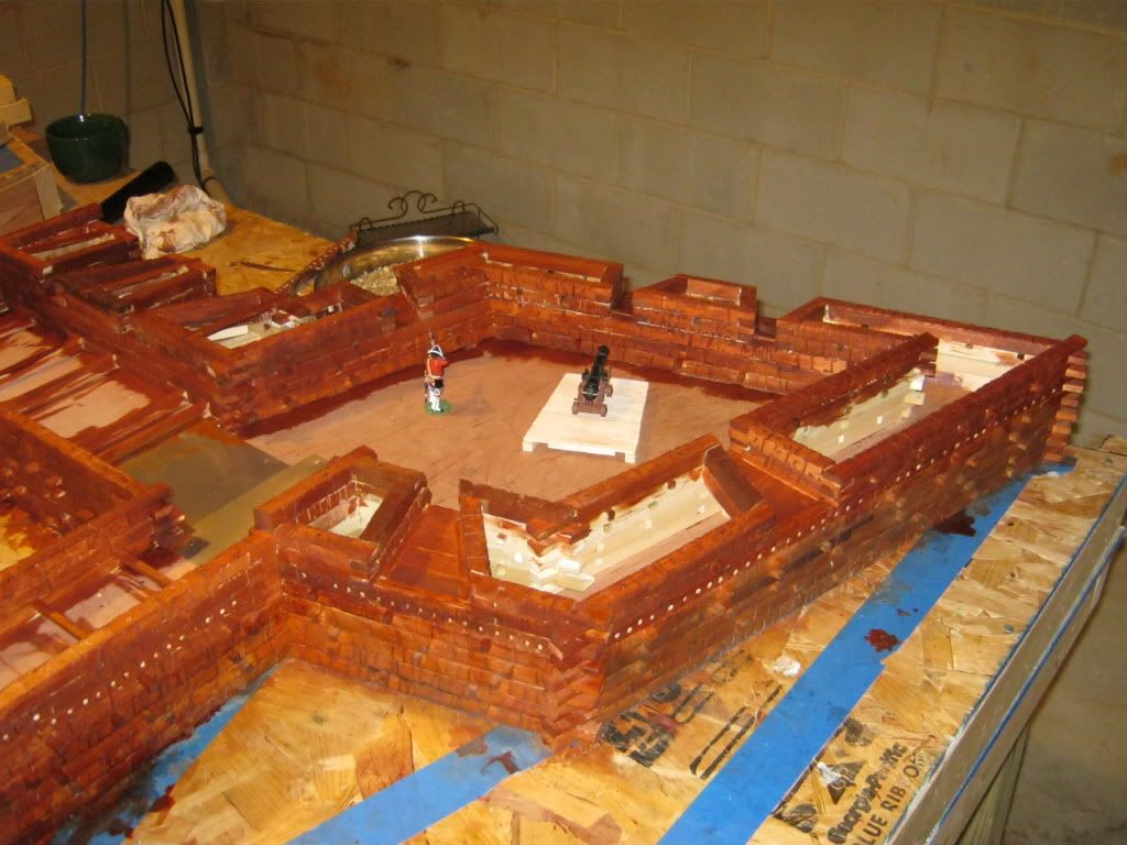
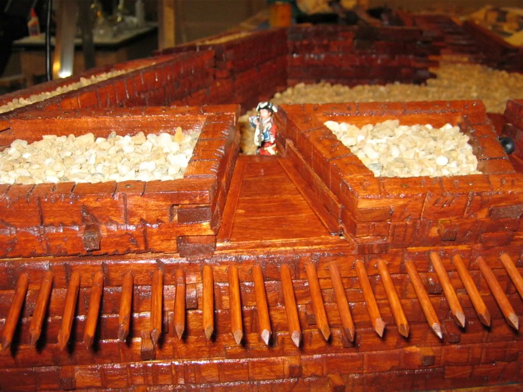
The wall construction is of horizontal logs – standard method for larger bastion forts in North America. I initially thought I would need a keyed stack joint, like lincoln logs, but I was never able to figure out how to do that type of joinery with any accuracy, especially as the joints needed are not 90 degrees. After staring at photos of Fort Ligonier for hours, I realized how the walls were constructed and decided I could use a lap joint as they do at Fort Ligonier. The use of the lap joints made the construction practical. Historically, the front and back walls of the ramparts and parapets are repeatedly connected to each other by logs internal to the wall, something like a basket weave. As such, there is an underlying support skeleton of timbers connecting the front wall to the back walls of the rampart. Once the wooden elements of the wall were assembled, the voids between the timbers were backfilled with earth and compacted. Understanding how the forts were actually constructed, allowed me to attempt this crude model. Without this understanding, I would not have attempted the model.
In some of the photos, there is a drop off in front of the outer walls. Eventually, this will be the framework for the perimeter ditch. Historically, the ditch served as the source of the fill material to construct the walls and was a key element in the defense. In the model, the ditch will only be on two sides of the fort. The other two sides lack the supporting ditch, but these sides are not likely to be attacked because the topography prevents it ---- there will be a lake, river, marsh, or steep cliff etc.
At this point, only about 20% - 25% of the total fort has been completed, one of the 4 bastions and segments of the adjacent curtain walls. I decided that it would be best to “finish” this 1 bastion and then see if I was enjoying myself enough to warrant completing the remaining 75%.
Below is a link to a scaled map of Fort William Henry including a cross-section on the wall.
http://www.masshist.org/maps/PlansandForts/PlansAndFortsp26.htm
I have been working on this fort since last July. Some of the elements you see have been suggested by Mike Miller. Compared to Mike, I work very slowly and sporadically. Construction is on the five-year plan. However, I promised Mike that I would post something on the forum before the end of 2010, so here goes ……
I have always been fascinated by fortification engineering, particularly bastion forts from the French & Indian War Period. Some after viewing UK Reb’s diorama pages and Mike Miller’s dioramas, I started researching into bastion fort design with the far back in the mind idea of someday modeling a bastion fort.
There was a web page Civil War Fortifications (defunk now) that contained a wealth of information via their Dictionary Page. Contained on that page were the guidelines and rules for developing fortifications including “tracing” a bastion fort --- developing the outline for a bastion fort. Although the outline of the bastion fort changes angles repeatedly, the outlining of the fort is very easy, it does not rely on drawing angles, but on simple intersecting lines. As such, developing the outline is straightforward and not at all difficult. The only angle that one needs to determine are 90 degree angles and any math involved is maybe 5th grade level.
I learned to trace bastion forts using this method of intersecting lines. Eventually, I took a protractor to my scale drawings to determine angles. I was surprised and very happy to find that there were only 2 resulting angles for a 4-sided bastion fort, 60 degrees and 75 degrees. Two of the standard hard stops on any miter box or power sander.
The principle idea behind a bastion fort is to have fields of fire to all points surrounding the fort and not have any defensive blind spots along the walls were an attacker could “hide” and not be fired upon by the defenders. At least from some vantage point on the wall, the defender has to be able to see and fire upon any attacking force that is hugging perimeter wall.
A B
D C
As such, the concept of a bastion fort is largely based on mutual protection - Bastion A protects the Walls of Bastion B and D while Bastion B protects the Walls of Bastion A and C, etc.
The fort I am modeling is not of a specific historical fort. But a fusion of several different concepts that were part of various forts constructed during the French & Indian War and the Revolutionary War – Fort Stanwix, Fort Ligioner, Fort Duquesne and Fort William Henry.
A principle concept of a bastion fort is to withstand some measure of artillery fire. As such, one determines what guns are likely to be used against the fort which then determines the thickness of the ramparts and parapets you need to build. Even if you assume a small caliber artillery piece such as a 6-pounder, the wall thickness to withstand a hit would be about 10 feet (6 feet penetration from the cannonball plus 50% more for a safety factor to allow the wall to remain standing). To accept the recoil from the defending artillery and have room to operate the gun, the artillery platforms behind the upper wall has to be at least 15 feet long. So if you are trying to utilize minimum values for your wall thicknesses, the wall thickness at the base is at least 25 feet (10 feet + 15 feet). At 60 mm scale, 25 feet = 10 inches. An upper parapet thickness of 15 feet would “allow” for attacking guns of a somewhat larger caliber, but the base wall thickness would then be increased to 30 feet (Fort William Henry).
The thickness of upper wall is critical in determining the overall dimensions of the fort. Again, the defense of any specific bastion is derived from the adjacent bastions. As such, you have to be able to “see” over the wall to ground level. Assuming a wall height of about 15 feet and an upper parapet thickness of 15 feet, the individual bastions have to be a minimum of 300-350 feet apart to eliminate any blind spots along the walls. If any closer, there will be safe spots adjacent to the walls were the defenders cannot see from neither of the adjacent bastions, never mind concentrating any defensive fire against that blind spot.
So unless you are willing to introduce a fatal flaw into the design, the minimum size for a bastion fort is 300 feet by 300 feet - (a better minimum would actually be a tad larger, Fort William Henry was about 325 by 350 feet). If taken to 60 scale, our model 300 ft. x 300 ft. structure is now 120 inches x 120 inches or 10 feet x 10 feet. This is simply too big to model.
But as the basement has a dehumidifier, not all hope was lost. After a lot of thought and delay, I decided to go for a 90 inch x 90 inch bastion fort (225 foot x 225 foot). The model would then by 7.5 feet x 7.5 feet. This is larger than Fort Duquesne (160 ft. x 160 ft.), but introduces a considerable number of design flaws (weaknesses) that are actually damm annoying. Dimensions smaller than 225 feet generate problems because the artillery platforms overlap (guns on recoil crashing into one another) and the flank gun embrasure is lost.
There are only three types of walls to a bastion fort. The long walls of the bastion = Face, short walls = Flank, and the walls connecting the various bastions are the Curtain Walls.
With the 225-foot design, things become very crowded, very fast. The square footage for a 225 x 225 foot is less than 60% of the 300 x 300 foot bastion. At 300 ft X 300 ft, the interior open space for the individual bastions would have been so much larger and much more attractive than the 225-ft design I ended up with. Excluding the wall thickness, the open space within the modeled 225-ft bastion is only about 15 inches by 15 inches.
Among the design flaws I introduced in order to save space is the reduction of the upper parapet thickness on the bastion walls from the desired 15 ft to 10 feet. I left the parapet thickness on the curtain wall at 15 feet. The gun platform length was left at 15 feet. With a 300-foot design, each bastion could have probably supported 7 guns comfortably, but only 5 guns at 225 ft. Losing a gun position on each face of the bastion hurts. Ideally, there should be 2 guns in each flank of the bastion, instead of the one gun, but getting 2 guns into the flanks probably would have needed at least a 350-foot design or 375-foot design. The guns located in the flanks are key to the defense. I could have squeezed in more gun embrasures, but they are very time consuming to build and I did not want to crowd the model. In most forts the number of embrasures (gun ports) far exceeded the actual number of cannon several times over.
Google Book is a great resource for historical military manuals and old books. Often non-copyrighted materials are fully viewable. Simply go into google book and start searches from there. I have again access to dozens of military engineering manuals and texts from the period 1700’s and 1800’s. From these sources, I developed a good idea about the construction of gun embrasures, dimensions and such. Here I cheated some, the narrow neck of the gun port should only be 2-foot wide - less than an inch at 60 scale (0.8 inches). In some cases, the narrow neck of the gun ports are considerably wider to allow a broader field of fire, but the military manuals of the time strongly advise against the narrow opening being more than 2-foot wide. Sometimes this wider neck was intentional to compensation for the low number of embrasures, other times - just sloppy construction on my part.
The wall construction is of horizontal logs – standard method for larger bastion forts in North America. I initially thought I would need a keyed stack joint, like lincoln logs, but I was never able to figure out how to do that type of joinery with any accuracy, especially as the joints needed are not 90 degrees. After staring at photos of Fort Ligonier for hours, I realized how the walls were constructed and decided I could use a lap joint as they do at Fort Ligonier. The use of the lap joints made the construction practical. Historically, the front and back walls of the ramparts and parapets are repeatedly connected to each other by logs internal to the wall, something like a basket weave. As such, there is an underlying support skeleton of timbers connecting the front wall to the back walls of the rampart. Once the wooden elements of the wall were assembled, the voids between the timbers were backfilled with earth and compacted. Understanding how the forts were actually constructed, allowed me to attempt this crude model. Without this understanding, I would not have attempted the model.
In some of the photos, there is a drop off in front of the outer walls. Eventually, this will be the framework for the perimeter ditch. Historically, the ditch served as the source of the fill material to construct the walls and was a key element in the defense. In the model, the ditch will only be on two sides of the fort. The other two sides lack the supporting ditch, but these sides are not likely to be attacked because the topography prevents it ---- there will be a lake, river, marsh, or steep cliff etc.
At this point, only about 20% - 25% of the total fort has been completed, one of the 4 bastions and segments of the adjacent curtain walls. I decided that it would be best to “finish” this 1 bastion and then see if I was enjoying myself enough to warrant completing the remaining 75%.
Below is a link to a scaled map of Fort William Henry including a cross-section on the wall.
http://www.masshist.org/maps/PlansandForts/PlansAndFortsp26.htm
I have been working on this fort since last July. Some of the elements you see have been suggested by Mike Miller. Compared to Mike, I work very slowly and sporadically. Construction is on the five-year plan. However, I promised Mike that I would post something on the forum before the end of 2010, so here goes ……