Building and detailing the M4A3 Sherman tank in 1/30th scale (5 Viewers)

Kenneth Osen

Private
Joined
Jun 30, 2025
Messages
34
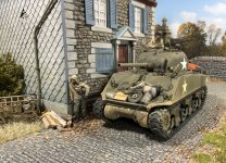
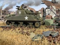
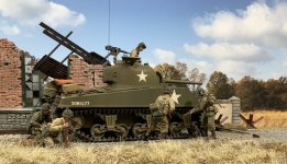
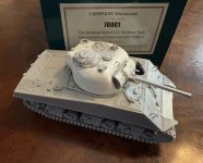
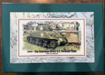
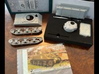
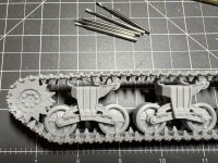
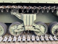
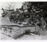
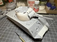
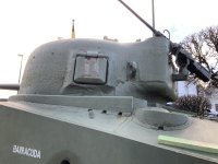
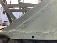
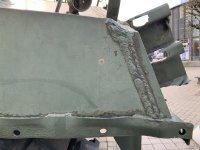
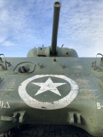
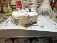
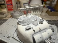
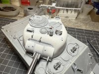
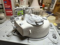
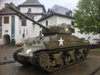
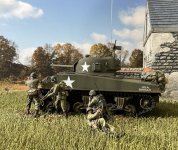
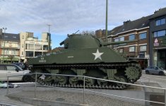
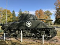
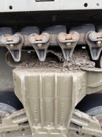
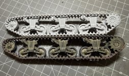
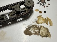
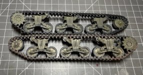
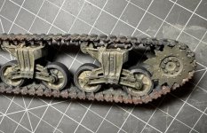
I have been working on a small group of M4A3 75mm armed medium (Sherman) tanks for a collector friend using the Campaign Miniatures resin kit I developed while was still working at W. Britain. Now that I am retired I have the luxury of spending time building and refining these vehicle kits to a much higher standard of detail than was intended with the original release. The original thought was to make these easy to assemble and finish kits that would allow collectors to add more than one vehicle to a diorama marked for the same unit. I suppose I always felt that was the advantage of building and finishing your own vehicles, but I also understand that some folks just don’t have the time. I included a few photos of the vehicle as it would look if built as-is right out of the box. It really looks the part just with a nice paint job, and when used with figures and scenic accessories it fills an important gap in many WWII collections in 1/30th scale.

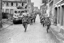
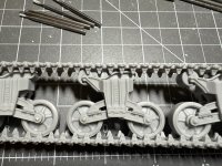
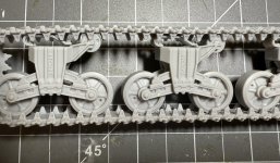
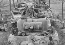
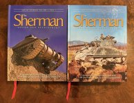
I also suspect that some may be intimidated trying to build and paint their own vehicle after seeing some of the excellent models routinely showing up on various modeling forums. But I think that with just basic modeling skills and a little practice almost anyone who wants to built a kit like this can get pretty nice results. I have been posting progress photos on my new Facebook page since retiring and moving to North Carolina and thought that some of you might be interested in seeing this build. I am weaving a story together that includes historical information combined with the techniques I am using during this project. I know that there are some very specific products now available for every possible step along the way, but I decided to proceed using fairly general products. I will try to post a new segment every few days, but for anyone that wishes to see everything to date feel free to visit my facebook page, Kenneth Osen The Gentleman Soldier.
 

Attachments

  • IMG_1698.jpeg
    IMG_1698.jpeg
    242.8 KB · Views: 31
  • IMG_3677.jpeg
    IMG_3677.jpeg
    192.3 KB · Views: 28
  • IMG_3310.jpeg
    IMG_3310.jpeg
    138.2 KB · Views: 28
A couple of years ago while working for W. Britain we decided to add some vehicles to our growing WWII collection. It seemed like everyone else in the collectibles industry was concentrating on every kind of vehicle the German army used, with little attention to the Allied armies. As we were focusing on the last few months of the war in western Europe it was pretty obvious that we should consider offering an M4 Sherman tank. Although we could have chosen any one of several models in that series that were deployed in combat at that time, the M4A3 with the new Ford GAA V8 motor seemed like the best choice. It became the preferred US Army version of the tank in both the 75mm and 76mm armed tanks, would see all the improvements and be the first hull type to take the HVSS suspension system into combat. The first production run of the GAA V8 engined M4A3 tanks were small hatch versions built by Ford, with most being used in the USA for training. With higher than expected tank losses during the Normandy Campaign some of these vehicles were rebuilt and sent to Europe and soldiered on to the end of the war side by side with newer variants. When Ford turned to other war work and the production was shifted to other makers the front hull was redesigned incorporating larger hatches for the driver and assistant driver/bow gunner and a change to the angle of the front plate to accommodate this new feature. This final variant of the hull would become the most iconic late war M4A3 armed with both the 75mm and 76mm guns and turrets. The M4A3 was produced in three factories with all turret types and armament with a total of 12,596 being built between June 42 and June of 45.
But back to modeling and how this project is a little different than the conventional approach. Part of our new product development process at W. Britain was to review the final components of any new project and then assemble them for painting in our studio. This allowed us to see how they worked with other parts of our collection and also allowed principle photography for packaging and website use. I have included one of those photos I took in this posting, and I think the various components worked together pretty well. When my co-worker Jef and I looked at the preassembled sub assemblies of the Sherman tank our first reaction was that the running gear assemblies looked great and we wished many of the 1/35th scale kits we had built could have been that fast and easy to complete. I am pretty sure that we are not the only modelers that hate removing parts from the plastic runners that kit components are molded on, and then cleaning them up before they can be put together. That is exactly what lead us to experiment with a 1/30th scale kit and the photo shows the result. This concept of pre-cleaned subassemblies eliminated the majority of the bench time required to identify, clean and assemble a tank model so you could get to the detailing and painting sooner, which honestly is the best part to me.
Some time after the finished models were released, I was commissioned to redecorate three of these M4A3 models to represent vehicles of a single unit operating together. I realized that building the kit versions for this project rather than stripping decals and redecorating finished models would allow me the opportunity to add additional details and individualize the stowage. The good news is that now that I have retired, most of the daily deadlines I had to deal with for over 30 years have been lifted. The benefit of this new reality is that I can now spend more time researching and incorporating the more creative elements of the process that I really enjoy. As this project advances I thought some of you might enjoy following the build, revisions, painting, weathering and the rational behind my choices. You can see that I have already applied new casting textures and am working on the hull welds with more details to be applied soon. I have to confess that I am enjoying this project so much that I am already thinking about detailing one of these kits for my own collection along with a fully realized scenic base. More to follow this week…
 

Attachments

  • IMG_0153.jpeg
    IMG_0153.jpeg
    159.1 KB · Views: 13
  • IMG_8806.jpeg
    IMG_8806.jpeg
    146.2 KB · Views: 13
  • IMG_6661.jpeg
    IMG_6661.jpeg
    110.8 KB · Views: 12
  • IMG_6662.png
    IMG_6662.png
    1.4 MB · Views: 13
One of the first areas I wanted to detail on these Shermans was the suspension system. Although this party of the kit is nicely modeled, some omissions were made to facilitate production casting in Polyurethane resin. Thinking about it when you look at many models in smaller scales we have an omnipresent view which accentuates the upper surfaces, but as a result the lower areas of the model are not always as prominent. However it is very different when viewing the real vehicles as we are typically at ground level looking up and that lower area is far more visible. The M3 and much of the M4 series used three bogie assemblies per side consisting of a central casting that held two road wheels on suspension arms, vertical volute springs, a return roller and in the M4 series, a track support skid. There were four stages in the development of this assembly but visually they are very similar in appearance. This type of suspension is known as the Vertical Volute Springs System and this is the system that will be represented on this model. I have included a photo of a page from the WWII US Army maintenance manual TM 9-748 showing all of the components in the VVSS bogie for clarity.

I have been fortunate to watch a few M3 Stuarts and M4 Shermans traverse relatively soft ground and I am amazed how fast damp soil will collect on certain parts of the running gear. To illustrate this detail I have included a wartime photo of a muddy M4A3 and a close up of a restored Sherman Firefly that was parked on the square in Bastogne during the 80th Anniversary.


I want to replicate this subtle collection of earth on these models and to do it justice I decided to remove the resin web that was cast in the center of the track skids to facilitate the removable of parts from the silicone production molds. This was actually pretty easy to do using an electric hand piece and a carbide milling bit. The preassembled tracks have enough flex in them that I was able to put a piece of 3/32nd brass tubing in between the skid and the teeth of the track to provide clearance for the hand piece bit when milling out the resin web. After the inside of the skid was cleaned up I simply removed the tubing and the track returned to rest on top of the skid. While working on these kit components I noticed the omission of several nuts and bolt heads that I wanted to add to each of the bogie assemblies. That ended up being straight forward by using plastic moldings originally made by the well know model railroad company Grandt Line. Each one was super glued in the correct location and when painted and weathered will enhance the realism of the running gear. I had to scrounge thru my parts to find enough for all three models so I decided to order some more only to find out that the company is now owned by San Juan Details. The order is hopefully on the way so I will have parts for my next round of tank detailing.


I know that there are some fantastic kits ranging from 1/48th to 1/16th that may be far more detailed, but these tanks were specifically designed to work with the pre painted metal figures currently available in 1/30th scale. This is not to imply that any one is better than the other, but this one works for its intended market and most of the hard work is already done. I think that when these kits are detailed and finished they will look every bit the part too. As far as when I build my own Sherman, I think I will construct some German village building facades to depict a tank with supporting infantry entering an older town, maybe with a medieval town gate, but that is still up the road a bit… more soon…
 

Attachments

  • IMG_3911.jpeg
    IMG_3911.jpeg
    89 KB · Views: 9
  • IMG_3910.png
    IMG_3910.png
    127.9 KB · Views: 8
  • IMG_8673.jpeg
    IMG_8673.jpeg
    204.6 KB · Views: 7
  • IMG_2516.jpeg
    IMG_2516.jpeg
    174.8 KB · Views: 10
  • IMG_8675.jpeg
    IMG_8675.jpeg
    205.1 KB · Views: 8
  • IMG_8877.jpeg
    IMG_8877.jpeg
    180.3 KB · Views: 11
Here is a photo of the model bogie assembly with the skid web removed, the bolt heads added and in the case of the road wheels the Zerc fittings and relief hole depressions added. I added this detail to the C85163 Stamped Spoke wheels but in some orientations you cannot see them because that section is hidden by the support arm. Much of the suspension will have mud applied so this may have not been necessary to add but I know they are there. They were pretty easy to simulate by using a small round burr in my electric hand piece to create the depression and drilling a small hole in the center to accept a .20 round headed rivet head made by Tichy Train Group. I still need to add the simulated grease fitting to the idler wheel.

Apparently there were six different types of road wheels used during the war on vehicles equipped with Vertical Volute Suspension Systems and this is the style we chose to use in the W. Britain model. We did include a type D52861 Smooth Concave wheel in one of the accessory sets for some variety and I will add the same fittings to those if I use them as spares on any of the tanks.

The Zerk fitting is something my dad introduced me to when I was a kid as he explained to me how to use the grease gun he had. The unusual name came from the inventor Oscar U. Zerk who was granted a patent for the small ball check valve used in the high pressure lubricating system of the Alemite Manufacturing Corporation. This small fitting was less vulnerable to dirt and because of the shape was more forgiving to an angled approach of the flexible steel grease gun tip. These were pretty universally used in vehicles built in the mid twentieth century, and on tanks they are often easy to spot because of the grease stains left around the relief valve. I included a couple of photos showing both of the wheel styles mentioned on restored vehicles, and I think the telltale grease stains will make a nice detail on the finished models…
 

Attachments

  • IMG_2518.jpeg
    IMG_2518.jpeg
    185.7 KB · Views: 5
  • IMG_8819.jpeg
    IMG_8819.jpeg
    159.4 KB · Views: 5
  • IMG_8673.jpeg
    IMG_8673.jpeg
    204.6 KB · Views: 5
  • IMG_7609.jpeg
    IMG_7609.jpeg
    139.4 KB · Views: 4
  • IMG_7303.jpeg
    IMG_7303.jpeg
    127.5 KB · Views: 4
  • IMG_3932.jpeg
    IMG_3932.jpeg
    168 KB · Views: 4
The welding of the hulls during production of the M4 was one of the most time consuming procedures that slowed up initial production. Traditionally this procedure required using highly skilled welders, but in order to speed up the process without compromising quality a new system was adopted. This divided the specific kinds of welds into individual categories that new hires would be trained in rather than be competent in every technique required in the tank assemblies. This significantly reduce the amount of time required for assembly, along with an improved use of jigs to weld components that could then be assembled as units. Many of the surviving tanks I have looked at have fairly obvious weld beads in numerous locations.
This weld bead detail has often been missing on scale models, and even when it is included in the tooling some modelers remove the molded on detail and replace it with epoxy putty or, more recently the use of decals with simulated raised weld beads. The Campaign Miniatures model has the traditional shallow groove molded in simulating the separate panels, so I decided to add the weld beads with epoxy putty. Overall this is pretty easy to do and I think it will look good when painted and I am nearly finished except for the smaller welds here and there.
I am also improving the texture that simulates the casting on the turret and the transmission housing at the front of the vehicle. I decided to add a bit more epoxy putty to the front right side of the turret casting as this area was thicker on production turrets for the wet stowage M4A3s. This is not always easy to see in photos because the welded guard around the turret on the hull covers this when viewing from ground level. Looking at the monument turrets during my last visit in and around Bastogne made this detail more obvious. I used Tamiya putty to add some thickness to this part of the turret casting and then used the same putty thinned with Testors liquid plastic cement to add the casting texture. This works really well and you simply thin it down and apply it with a brush using a stippling motion. If any part of the “casting” surface appears too pronounced when it drys it can be reduced with fine emery paper.
Another even more surprising surface detail on many Shermans are the crude grinding marks left from cleaning up the casting gates on the turrets and transmission housings during manufacturing. This detail is something I hope to add to at least one example but as my co-worker Jef and I always thought, those that did not understand what this represented might take it for very bad modeling! I have included a few additional photos of monument tanks that show areas where the evidence this grinding shows.
 

Attachments

  • IMG_8828.jpeg
    IMG_8828.jpeg
    175.1 KB · Views: 7
  • IMG_2536.jpeg
    IMG_2536.jpeg
    123 KB · Views: 6
  • IMG_2526.jpeg
    IMG_2526.jpeg
    113.7 KB · Views: 6
  • IMG_2542.jpeg
    IMG_2542.jpeg
    124.5 KB · Views: 6
  • IMG_2570.jpeg
    IMG_2570.jpeg
    118.3 KB · Views: 7
Embarrassingly enough, a lot of the technical details are lost on me. But my subconscious registers them and they, for me, separate a tank model from a miniaturized real tank. Latter immediately demand attention and respect and in any modeling show stick out. If AFV modeling switched from 1/32 or 1/35 to 1/30, I would be all in.
 
At this point I pretty much finished adding the details to the turret and I think it is a lot more interesting with the small items often overlooked. The next step will be smoothing any unwanted marks or glue and priming it with black acrylic paint to inspect the surface before the first shade of O.D. Green. The most fiddly parts were probably for the M2 .50 Machine gun. I lengthened the machine gun pedestal, added the pintle locking handle and made the folding base and hinge. I added the pivoting barrel travel lock after bending and folding three of the barrel clips out of thin copper before I got it right… two more to go now. I also detailed the M2 stowage array at the rear of the turret. This consists of the cast socket that comes with the kit and adding a locking handle to it. The bracket that held the cooling jacket of the gun was a bit more tricky as I wanted it to be durable, so I decided to use the steel staples from my Arrow stapler re-bent to duplicate the triangular bracket. To insure that it was anchored firmly I used two staples, one shaped for the upper bracket including the semi circular retainer, and a second one for the lower part so both could be glued into holes I drilled into the rear of the turret. The spring clip was simulated with a modified model railroad nut-bolt-washer casting and the hinge with a thin piece of round plastic.
I detailed the cover for the gunner’s periscope with some rivets and evergreen plastic and added the commander’s vane sight using a combination of another steel staple and evergreen plastic with some model railroad rivets. In many of the photos the turret spotlight is turned with the lens facing down, so I decided that the quick fix was to drill into the casting, insert a shortened steel shirt pin, then use a micro saw to cut the resin where it meets the light housing so I could spin the light down and secure it with superglue. I suppose I could have left it movable but I worried about it coming off.
I also added the muzzle of the M3 2-inch breech loading mortar with muzzle cover in place on the left upper section of the turret. These were apparently disliked by the U.S. crews and they were discontinued in the later production D78461 turrets. I have a few things to do to prep the hull for the final details and that included filling some of the mounting holes with epoxy putty so I can add more refined details…more on that part of the project soon…
 

Attachments

  • IMG_4041.jpeg
    IMG_4041.jpeg
    102.7 KB · Views: 5
  • IMG_8879.jpeg
    IMG_8879.jpeg
    126.5 KB · Views: 4
  • IMG_8877.jpeg
    IMG_8877.jpeg
    131.9 KB · Views: 5
  • IMG_8878.jpeg
    IMG_8878.jpeg
    155.7 KB · Views: 4
  • IMG_8874.jpeg
    IMG_8874.jpeg
    135.7 KB · Views: 5
The 9th arrived to the ETO in the months just before the Ardennes offensive and the three Combat commands were placed in forward positions to get some experience in the field in this quiet sector. When the German’s launched their offensive on December 16th the 9th AD was immediately engulfed in the hard fighting along the front. Photographic evidence indicates that most of the Shermans were M4A3 76mm armed Wet Stowage vehicles in the Ardennes, but both film footage and photos taken in the closing months of the war also include M4A3 75mm armed tanks and if the photographer’s notes were correct on some film footage, even a few cast hull M4A1 76mm armed vehicles. Another interesting detail is that almost all of the tanks seem to have been field modified at unit level to include bars welded to the turret to hang stowage such as musette bags and in some cases the metal Grousers that were used much the same as tire chains on cars to provide extra traction on snow and ice for the tracks. Additionally, many of the tanks had round steel bar welded to the front and sides of the hull and on either side of the turret so thin wire Sommerfield Matting could be welded in place to facilitate adding camouflage to the tanks.
The 9th AD returned to Remagen for a ceremony on May 15th 1945 and a Signal Corps film records M4A3 76mm armed Sherman tanks with the details mentioned on all of the vehicles. It is also worthy to note that none of them in this film seem to have white recognition stars on the hull or turret sides. The remnants of these same modifications are also evident on a surviving 9th AD tank that was knocked out in Clervaux, Luxembourg that is now there as a monument. These added features may have been fairly common at this point of the war as same treatment also appears on vehicles identified as being part of the 4th, 6th and 7th Armored Divisions, and possibly more.
Most of the 76mm and 105mm armed tanks of the 9th AD also sport at least one dark color, probably black, over-sprayed in a large disruptive pattern. Some reconstructions show a second lighter green added to the overall olive and black pattern on the tanks and maybe someone out there knows the primary source for this scheme. The photos of the 75mm armed tanks seem to be overall Olive Drab, but dust, mud and low contrast Black & White photography also make multiple colors schemes hard to make out. If the M4A3 (76) model is eventually released by W. Britain I hope to get a couple to add these details too.
These reworked Campaign Miniatures M4A3 (75) Wet Stowage kits will represent vehicles of the 9th Armored Division toward the end of the war. I am using a photograph taken in April of 1945 of M4A3 (75) W tanks at Westhausen, Germany as my inspiration for these and I will stow them in a similar fashion with the spare tracks on the front Glacis plate. I am guessing that these are vehicles replacing the 30 or so tanks lost in the race to the Rhine and the capture of the Ludendorff Bridge at Remagen, Germany. I hope some of you are enjoying these ramblings…
 

Attachments

  • IMG_5728.jpeg
    IMG_5728.jpeg
    135.7 KB · Views: 3
  • IMG_8855.jpeg
    IMG_8855.jpeg
    130.9 KB · Views: 4
  • IMG_3425.jpeg
    IMG_3425.jpeg
    163.3 KB · Views: 4
  • IMG_6676.jpeg
    IMG_6676.jpeg
    122.2 KB · Views: 4
  • IMG_5413.jpeg
    IMG_5413.jpeg
    125.9 KB · Views: 3
During WWII the U.S. Army issued Air Identification Panels for front line troops made from heavy plasticized material with neon red or neon yellow one side and white on the other. The panels were in two sizes, approximately 30" x 72" or 30" x 120". All panels were white on the reverse side which allowed messages or other markings to be added. There were recognized patterns in the manuals that allowed a number of panels to be arranged to indicate wind direction for airborne troops or to mark friendly positions to Allied aircraft. This style of recognition panel was also specified as part of the “On Board Stowage” for all armored vehicles, as well as many soft skinned vehicles if they were near the front lines. Once the US acquired air superiority in Europe after the Invasion, most vehicles operating near the front lines used these panels, but even with this piece of equipment there were incidents of U.S. vehicles being attacked by Allied fighter bombers. The color, or combinations of colors would be ordered for a few days use to allow for implementation and communication to combined arms.
Once you know what you are looking for you can spot these panels in many WWII Signal Corps photos and movies but because of the Black & White photography they are easy to miss. The easiest way to spot them in period photos is to look for the darker edge binding on the very light contrasting panel draped over stowage on the rear deck. In one newsreel I watched a column of M3A1 halftracks rolling by the camera man that had two panels draped on top of the rear stowage racks. Some years ago when the late war color films made by George Steven’s crew were released this detail really jumped out against the drab colored vehicles and stowage. In one short sequence a 2 1/2 ton truck appeared to have the bright blue one displayed on the canvas top, but I have read that this was used to indicate a lead vehicle on a convoy. These color films are now easy to find on YouTube and are well worth watching for details.
These panel sets were carried in an Olive Drab canvas CS-150 bag that closed with either two web straps or lift-the-dot fasteners. The canvas bag was also fitted with a shoulder strap for carrying. There were normally two panels of the same color per set marked ‘R’ for the AL-140 Red and ‘Y’ for the AL-141 Yellow, with both having white on the reverse side. The panels were edged with dark brown tape along the edges and included metal grommets at intervals. Often olive drab tapes were also included to secure them to a vehicle or to stake them down. Another accessory that was included were wooden dowel rods to roll the panels up on.
Later in the war single panels were also issued that rolled up into an Olive Drab canvas bag attached to one end that closed with lift-the-dot fasteners and were labeled AL-140B or AL141B. This style are often visible in newsreels and period photos when you look for them.
The label text on the bag for storing the panels is interesting:
“Instructions for Field Care”
1. Do not expose the Neon-red side of the panel to sunlight unnecessarily.
2. In cleaning this panel wipe with cloth or sponge soaked in gasoline or water.
3. Do not wrinkle or fold panel unnecessarily.
4. Do not wring out panel.
5. Do not use lye soap for cleaning panel.
Now the color as described in the period descriptions seems a little misleading to me, because the AL-140 Red panels actually appear as bright neon pink and the AL-141 Yellow panels can be close to neon orange, although they are not consistent. I have not been able to find out what the designation number was for the electric blue panels.
Clearly because of the warnings printed on the labels these colors were fugitive and would fade in constant exposure to UV light. I also suspect that the material degraded and made it prone to damage as indicated by the photo of the tear on one recently listed for sale.
When I was working at W. Britain we designed the stowage for our WWII armor to include these identification panels, and they seemed jarring at first only because the majority of the photos we see from WWII are in Black & White. Now that we can recognize them in period photos they are an important detail in a finished model and I have included a small diorama I set up of infantry supporting a tank. I thought it might be useful to explain this often overlooked item and why I will be including it on the three M4A3 tanks I am currently working on. I also thought it was interesting that this style accessory continued to be issued in the post war period and is still issued in a smaller form today as the VS17, with grommets and snaps to create larger panels if needed. The new laminated panels are lightweight compared to the WWII versions and are fluorescent orange on one side and fluorescent pink on the other, I am not sure but they may also be infrared . I have been told by some veterans that these were often referred to as a “Don’t Shoot Me!” Panels… and I am guessing that their predecessors thought of their I.D. Panels in the same way!
 

Attachments

  • IMG_5131.jpeg
    IMG_5131.jpeg
    248.5 KB · Views: 6
  • IMG_4391.jpeg
    IMG_4391.jpeg
    69.8 KB · Views: 6
  • IMG_4386.jpeg
    IMG_4386.jpeg
    54.7 KB · Views: 3
  • IMG_4385.jpeg
    IMG_4385.jpeg
    113 KB · Views: 4
  • IMG_6122.jpeg
    IMG_6122.jpeg
    122.2 KB · Views: 6
So, when looking at photos of U.S. WWII Sherman tanks they generally all seem to look the same. But if you study photographs they also can look very different from each other, and sometimes you will even see two distinctly different production variants in one unit. This is largely because many of the main components in the M4 series evolved during the war and some models share very similar if not identical components. There a few important details that stand out to even the most casual viewers and I will touch upon just the basic points of some of these features over the next couple of days so I can zoom in on my current project. There are versions of the tanks with rounded cast hulls, others with flat slabs of armor plate making up the welded hull variants, different types of main armaments, and finally the changes in suspension systems.
All this stuff was a mystery to me too until I purchased a book published in 1978 by R.P. Hunnicutt, SHERMAN A History of the American Medium Tank. This was pretty much the bible on the Sherman tank and there is some really solid information and although I have to admit it is not an easy read, it is still an important addition to my library. Perhaps the best publication on this subject to date was written by Patrick A. Stansell, and I purchased both the first edition and the updated second edition in 2 volumes. If you decide you really want to dive into this iconic vehicle I suggest you get your hands on a copy of: The Sherman Design and Development - A complete and illustrated description of the U.S. Sherman tank series in the Second World War (ISBN: 978-0-9773781-3-5) With that said I have run into several enthusiasts that know more off the top of their heads than I can ever hope to know.
So circling back to the current project on my bench, I am building and detailing the M4A3 75mm armed variant of this tank in U.S. service as it would have appeared in the closing days of the war in Europe. In the next couple of days I will give a little more detail on what kit I am using and how I am improving various details to better represent these wartime vehicles, including stowage and crews.
I have included photos of two monument M4A3 tanks, one of the earlier variants in Chillicothe, Ohio and an important M4A3 Large Hatch tank on the square in Bastogne, Belgium. This last one, along with other full and partial examples in the Ardennes have been very useful for my current project and I have been able to photograph the details on most of them a couple of times in the last few years.
 

Attachments

  • IMG_6711.jpeg
    IMG_6711.jpeg
    267.4 KB · Views: 0
  • IMG_6713.jpeg
    IMG_6713.jpeg
    207.5 KB · Views: 0
  • IMG_6712.jpeg
    IMG_6712.jpeg
    204.1 KB · Views: 0
  • IMG_6710.jpeg
    IMG_6710.jpeg
    129.9 KB · Views: 0

Users who are viewing this thread

Back
Top